I have been wanting to add a dual batter setup for some time. Not for winching (at this time) but for accessories. I recently added a battery management device to my trailer, and thought it would be a good way of managing my dual battery setup too. For the battery location, I decided to find a second tray to put in the factory location. I found it at Stainlesstrays.com. For the price of a new tray for the drivers side from some places, I was able to get two new stainless steel trays. The original one was looking a little worse for ware.
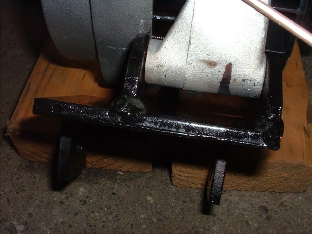
The new and the old side-by-side
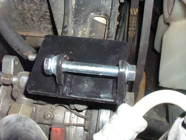
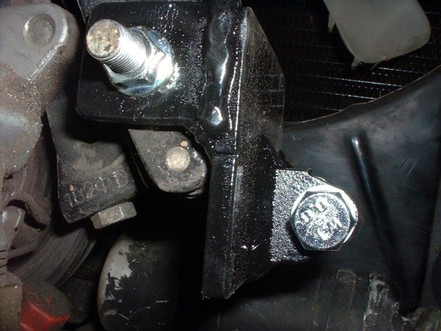
Here are the pictures of the new trays installed.
I don’t have the second battery or management device yet, so I haven’t figured out were I want to put the radiator overflow tank.
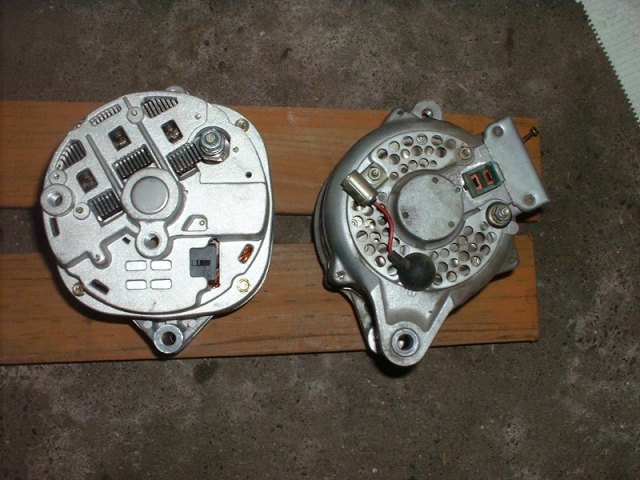
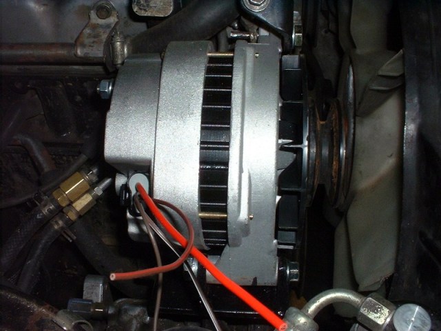
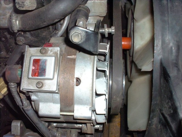
Since the addition of my TBI, Halogen lights, GPS, CB and other assorted accessories, I worried about the ability of my stock alternator to keep up with the demand. After doing much reading and searching on MUD I decided the Delco Remy CS 144 (big brother to the cs 130 but wired/mounted the same way) would fit the bill perfectly. I purchased it from Alternator Parts. It is available in the 12 o’clock/6 o’clock mounting style, just like the Denso. It also has a 17mm shaft, so the stock pulley fits right on too (but you have to use the nut that came with the alternator). I also chose to use the 5 wire alternator rather than the 1 wire because I wanted my “charge” lamp to work. I also read that the 1 wire alternator doesn’t sense the system voltage the same was and can take higher RPMs to activate the field and start producing electricity. I opted for the 140 amp version but was told it would actually produce closer to 175 amps.
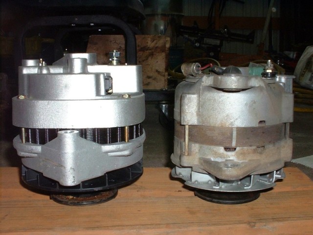
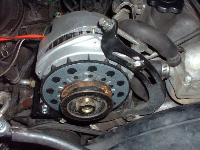
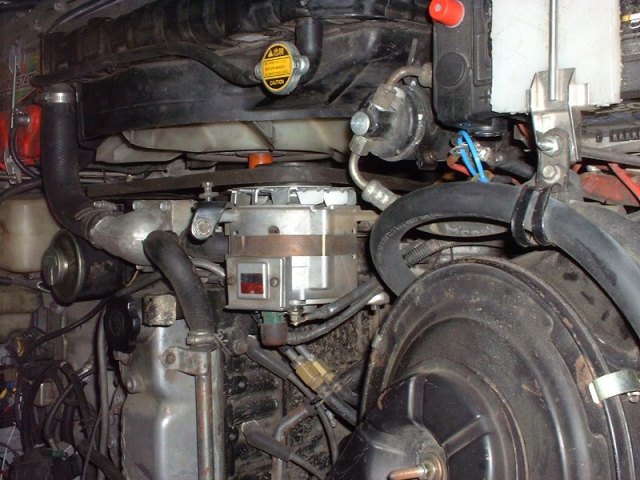
Here are a few pictures of the difference between the two alternators.
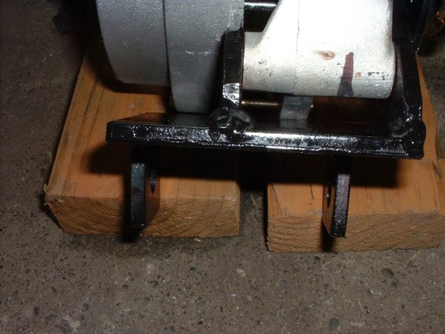
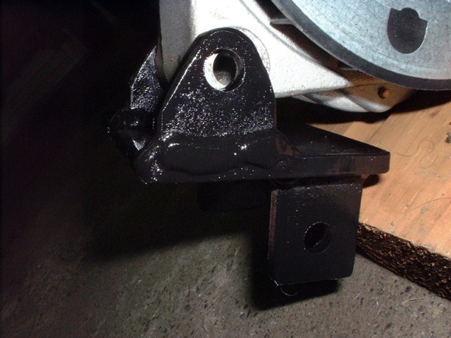
The bracket was made from a piece of 3″ x 1/4″ flat stock. I just measured from the front of the pulley on both alternators, relative to their mounts and welded tabs to a 4″ long piece of the flat stock.
I was able to use the stock adjuster by turning down the end of a bolt, just like the factory one. The cs 144 uses a larger bolt on the adjusting end.
Last thing was to find a belt that would fit. I fount a slightly longer one at Napa (25-22648).
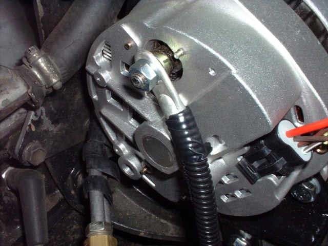
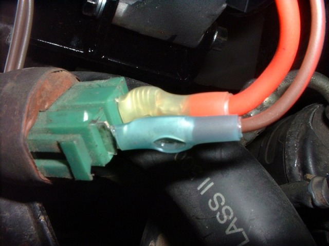
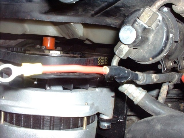
Wiring was not that dificult. I used a 4 ga battery cable from the alternator to the pos post of the battery to help carry the new found amperage. I only needed two of the four wires on the cs 144 pigtail harness. The large red wire is the “S” terminal and can either be connected to the “B” post on the alternator or to the “IG” terminal on the stock wiring harness connector. The “L” terminal on the cs 144 goes to the “L” position on the stock harness connector and is for the charge light. Lastly, don’t forget to hook the wires on the wring terminal formaly connected to the “B” post of the factory alternator to either the battery pos post or the “B” post on the back of the new alternator. I connected it to the battery.
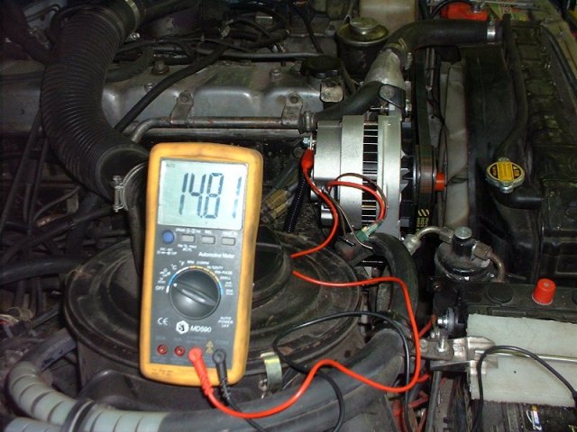
Finaly a before and after comparison. I forgot to record the before alternator output, but after is pretty good at 14.8 volts at idle.
I started this project in late 2001. I spent many hours combing the wrecking yards looking for parts. As money was short and I had a lot of time, I picked almost all of the components from the wrecking yard.
First I would like to give credit to a few sites that really made my project work. Tom Quinn published his page just as I was starting to gather pieces. Another site is CustomEFIS. If I were to do this project again and had a little more money, I would buy one of his setups. He is cheaper than the other guys and has outstanding customer service.
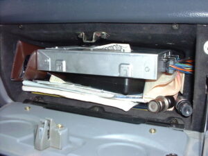
ECM (1227747 out of an 91 Astro Van) in the glove box.
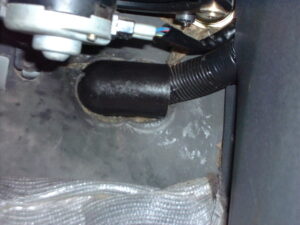
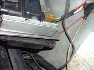
GM wiring harness at the passengers feet. This harness was pulled out of an S10 (I actually pulled two harnesses and soldered them together for the correct lengths on all wires). It only took me 1 hour for the pair (the second one was easy because I didn’t need anything beyond the firewall. The S10 has a round rubber grommet built into the harness and a plastic cover on the inside.
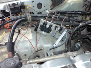
Coil, igniter, relays and fuses. The igniter is mounted in a VW Jetta igniter heat sink (from ’91 I think). I made a bracket to mount this all in the stock position. The ESC is mounted on the back side. Since I was using a GM wiring harness, I just kept the fuel pump relay. I used another GM relay to switch my “ignition on” power. All ECM power comes from the battery through 30 amp circuit breaker, then two 10 amp fuses (one for each power lead).
Distributor. For the distributor I followed the steps on Tom Quinn’s (cruiser specific) page and CustomEFIS (has great detail on the how and why, but you have to buy the ebook). The distributor is set to the standard 7deg BTDC (the BB).
MAP sensor and vacuum connections. I blocked of the PCV port because my PCV hose is routed to a port in the intake by the EGR.
Throttle cable bracket and adapter plate. I used a stock GM throttle cable and modified my gas peddle to work with it. I made my own adapter plate out of three pieces of 1/2″aluminum plate. A note for FJ60s. I wouldn’t use more than 1″ of total adapter if you are keeping the insulator and want to use an open element filter. The stud for securing the top of the filter housing is just long enough to make a nice bump on the hood (found out the wrong way). Mine is rough but only cost about $20 ($3 for the aluminum, $6 for the tap, and $11 for the hole saw). I have some drawings that I will try and get up here if I ever figure out how to export from the drafting program. Here is the dwg file for the adapter. One thing to check while you have everything off of the intake is it’s bottom. After chasing a vacuum leak, I found out the bottom of the manifold was cracked (common with these intake/exhaust manifolds). When remounting the adapter plates this second time, I cut gaskets to go between each plate to seal better. I just picked up the thickest stuff at the parts store (about as thick as the throttle body gasket).
There is now a very nicely finished adapter available from Mike Smythe on his web site. If it would have been available when I was trying to wrap up my project I would have gotten one. (Mike is not currently able to produce more of these adapters).
The throttle cable bracket is mounted to the adapter and can move for adjustments, since the GM cable isn’t threaded with adjuster nuts.
UPDATE: I eventual changed to the mounting adapter from Man-A-Fre. It is a very nicely done piece, and if it had been available when I started my project, I wouldn’t have had to modify my air cleaner assembly because they also have an air cleaner adapter. Check it out here. One of these days I will get a picture of the updated setup.
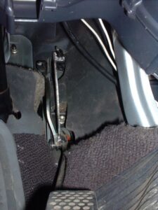
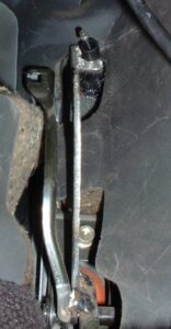
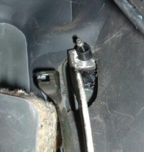
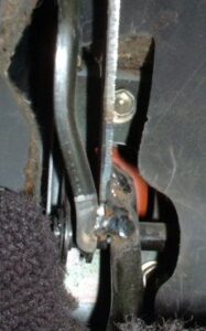
Gas peddle. My vehicle originally had a mechanical linkage rather than a cable, so some modification was in order. The original gas peddle was modified by adding another arm (next to the hand throttle connecting rod). It is an approximate copy of the hand throttle arm, lengthened to reach the point on the fire wall were the cable entered the cab. On the ’87 FJ60 there is an indentation in the sheet metal I assume is the mounting point for the FJ62. That is where I chose to punch my whole. I originally wanted to use a cable out of a Toyota pickup, but my TB has a different attachment point. On other TBs I’ve seen the Toyota cable would work fine. I thought I would be able to use a peddle out of a FJ62, but the mounting holes don’t match up.
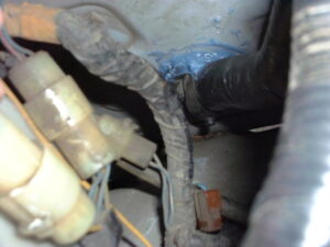
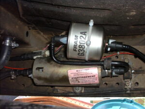
Fuel pump and connectors from an ’84 Ford Thunderbird (with mounting bracket). The 60 has much more room to mount a fuel pump due to the long frame. The pump is mounted just behind were the rear heater hoses enter the body. I used the stock hose to quick connect the filter. It is a ‘S’ shaped hose that allows the filter to be mounted over the pump.
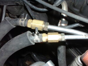
I used a Fuel line repair kit from the Help section at the local auto parts store to connect to the TB. I then bent the lines, connected them to an additional length of hard fuel line, then used 3/8″ barbed fittings to connect to the stock fuel feed and return lines near the original location.
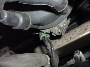
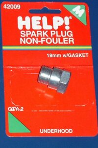
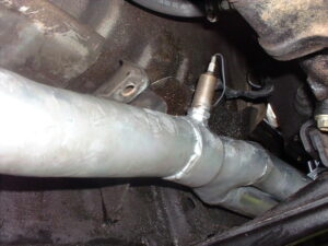
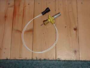
Emissions, EGR vacuum switch and O2 sensor. The O2 sensor is mounted in a spark plug anti fowler from Shucks (2 for $2.95, Motormite part# 42009). Just cut off above the threads. It needs to be the 18mm thread size. I am now using a 3 wire heated O2 sensor connected to the engine wiring harness with a little harness I made up. The O2 sensor I am using is Borg Warner part # OS120. It has a weather pac connector. The three wires are black (O2 Sensor wire from ECM – purple) and two white (one for chassis ground and the other for switched +12v power). I used white and red on my harness for the heated function (plus the purple to plug into the factory harness without having to cut and splice). This may seem like a lot of extra work up front, but will make it much easier when replacing sensors down the road and will be more versatile should I decide to go 4 wire (just make another harness).
Originally I wanted to retain the air injection stuff, but my air rail got mangled when I was taking everything off. Also, once I started fitting everything, it looked like it would be in the way. I may revisit this at a later date (with something like Man-a-fre’s air rail modified for the Webber carb. As far as the air pump, it is still there, I just connected two pieces of heater hose together to make a closed loop. Hopefully it will hold together.
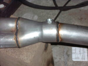
I kept the EGR valve and used a GM vacuum valve out of a 91 Astro van. All the other EGR stuff can go. As far as I understand, the MAP, Temp and O2 sensors take care of all the functions. I recently installed a set of Man-a-fre’s tuned ceramic headers (they have a fitting for EGR) but haven’t hooked the EGR back up.
Charcoal canister. The switch was bypassed with a 3/8″ vacuum fitting and connected to the appropriate port on the TBI.
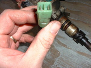
VSS. After several attempts at making my own buffer (see diagram) I decided to just get one from Jags that Run (also known as V8S10). They have one for the Toyota, and it was a simple connection. Now the ECM finally has speed. I’m told that this isn’t necessary for the conversion, but since I was retaining EGR I thought it would be a good idea. It also is need if you decided to play with the highway mode tuning (better gas mileage?). I eventually upgraded the VSS.
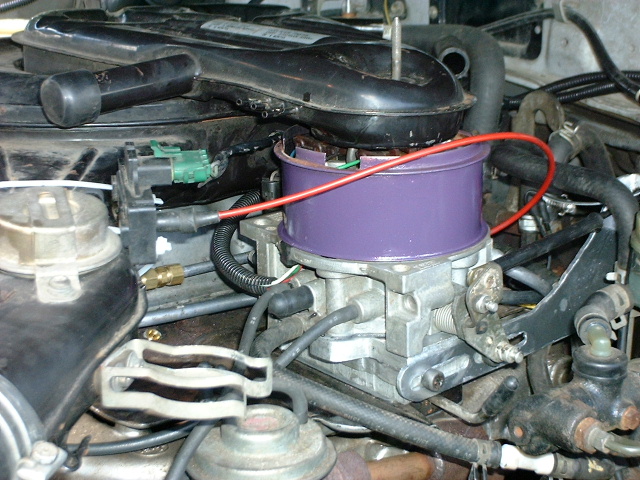
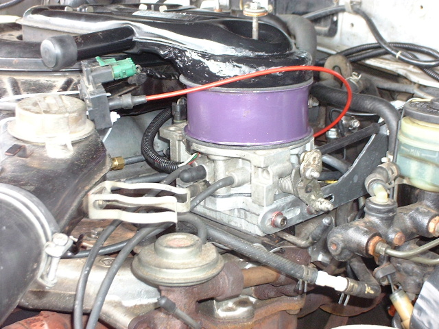
The air cleaner adapter is a stock van air cleaner mounting piece (spacer). It goes between the TB and the air cleaner housing. For the Toyota air cleaner, I cut out the base of a GM air cleaner housing (another spacer would work too) and welded it to the Toyota piece. Very rough, but like the TB adapter, it works and was cheap.
UPDATE: When I changed to the MAF moutning plate, I also switch to the cyclonic type air filter found on non-US trucks. I figured out that the Canadian Diesels also used this filter housing, so I picked up a pair of tops from EBI in Port Moody, B.C. One went on the FJ62 air cleaner housing I had already purchased (but I could have just gotten the complete unit from EBI). The second was trimmed down to just the small part and it fit perfectly on the TBI air cleaner adapter (purple in picture below). No updated pictures yet so check back soon.
The check engine (SES) light was mounted in the hole where the choke cable once resided. I found a little red one that fit the hole perfectly at Schuck’s.
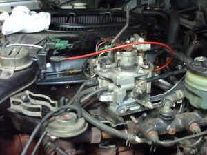
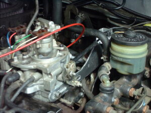
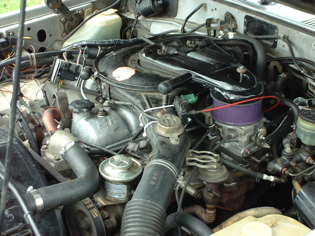
The finished product.
For the program to make it all run, I got help from Chet Wagner and John at CustomEFIS. Chet is on the Land Cruiser Mailing List. He has done a lot of work and tuning to put this chip together. John was integral in my learning what to adjust in the computer chip to improve performance. For my tuning I use WinALDL as the scan tool and TunerCat to reprogram the chip. I then use the Pocket programmer to burn new chips. My chip is programmed based on WinALDL data on my ’87 FJ60 with 2F (not currently using the EGR) and headers. Here is a spreadsheet I put together to help with transfer of info from WinALDL to TunerCat (Fuel table changes for Tuner CATS from WinALDL.xls).
First, I was told to do all the tuning with the EGR disabled (both in the bin and manual). Once you are done tuning, turn EGR back on and the ECM will compensate for it. Otherwise you will not be able to create a smooth fuel table.
The spreadsheet made it much easier for me to implement the changes from WinALDL. I make my run with WinALDL, save the BLM table (it gets saved as a text file). When I get home, I copy the current “Main Fuel Table #1” from TunerCat and paste it to the spreadsheet on the “Old Tuner Fuel tables” tab in my spreadsheet (VE#1 only, VE#2 is left alone). I then open the date_time_BLM.txt file in Excel converting it to a spreadsheet (Deleminated/Tab/General (column format)). I then copy ALL of the new spread sheet onto the “ALDL BLM Values” tab. You can now copy the “Combined Cor ave VE” tab into TunerCat (or what ever bin editing program you are using). The graphs in the spread sheet aren’t exactly like the ones in TunerCat. The spreadsheet calculates the new changes on BLM table data points with more than 3 narrow samples. If there aren’t more than 3 narrow samples, then it looks at the wide values with more than 6 wide samples. Otherwise the table isn’t changed at that cell.


")
")