Categories
Overland travel Tech Vehicles

Communications Upgrades

In my Land Cruiser I use a CB radio and Cell phone for most on road and trail communications. Around camp and hiking I use a FRS/GMRS radio. I decided to make a few upgrades in the Land Cruiser to make communication easier and more reliable.

For the cell phone, I have added a Wilson Electronics 3 watt booster and external antenna. At the time they didn’t have the cradle, but my old Motorola phone had an antenna port in the back. Now, they have a complete kit with external antenna, booster, wiring and universal cradle. The cradle has the inside antenna and will work with any phone, regardless of antenna port. I am using mine with the Motorola Droid. While just an external antenna can increase cell phone reception markedly, the 3 watt booster really gets your signal back out to the tower. Even when I don’t have enough signal for voice communication, I can usually send and receive text messages.

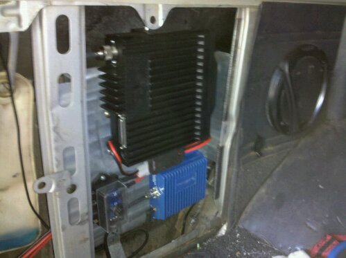
I originally had the booster just sitting under the drivers seat, an extension for the outside antenna, and the cell phone plug. I have been using the cradle for a while and love it. I’m doing some other comms work (keep reading), so I have decided to relocate the booster the the rear quarter panel. The power connector is just long enough, I moved the extension cable from the outside antenna, to the inside antenna/cradle.

One other modification I made to the cradle was to add a small magnet to correspond with the Droids sensor, making it my in car navigation as well as communications device. I will write more on this in another article.

For the GMRS radio, I went to GMRSOutlet.com were I found the Icom F2821 on clearance price. This radio is capable of GMRS, Business and

70cm communication. I had it programmed for GMRS, but also got the programming cable and software. It supports both CTCSS and DTCS tones for privacy communications. Remember, CTCSS and DTCS don’t keep others from hearing your conversations, just keeps them from interrupting you.

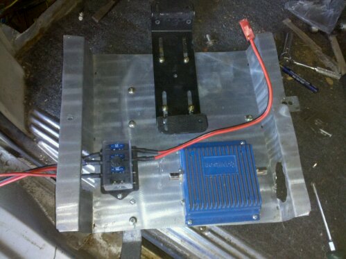
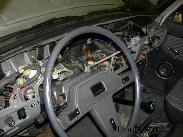
Because of mounting space, I decided to get the separation kit to mount the radio next to the phone booster in the rear quarter panel. With a removable face, the controls can be mounted in front. The only problem with mounting the main radio unit in the back, is the power demands. It needs direct battery connection, or at least a 10 gauge wire with 20amp protection.

I also wanted to add a power point for an ARB Fridge. so I decided to run some big power to the back. I already have dual batteries, so getting enough power won’t be a problem. I am running some 6 gauge wire to the back. I already have a 12 gauge wire running for trailer power and auxiliary backup lights, but that’s not enough power. I installed an extra fuse block in the back. Both the positive and negative line to the radio needs a 20 amp fuse. The fridge is on a separate circuit, and the trailer charge wire will be moved to run from the last fuse on the block.

image

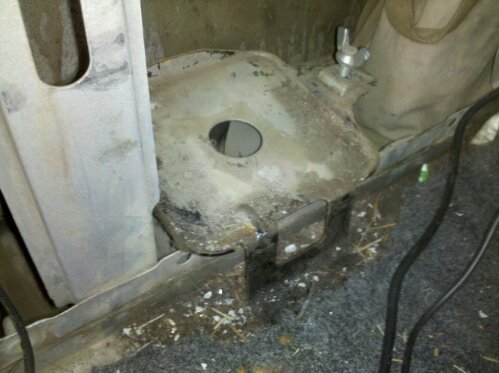
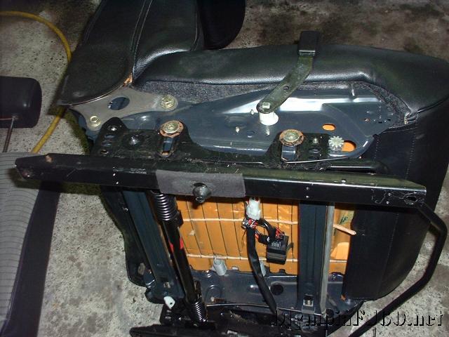
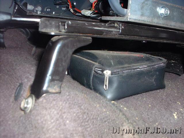
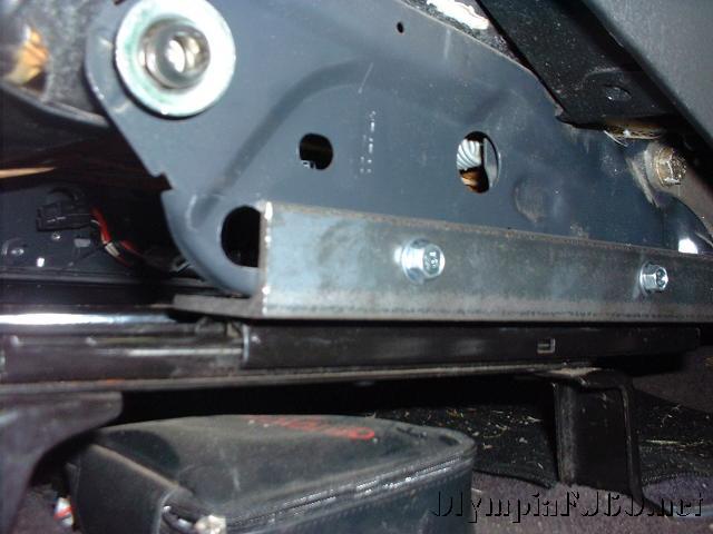
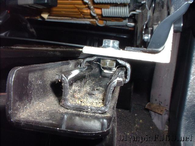
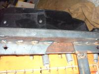
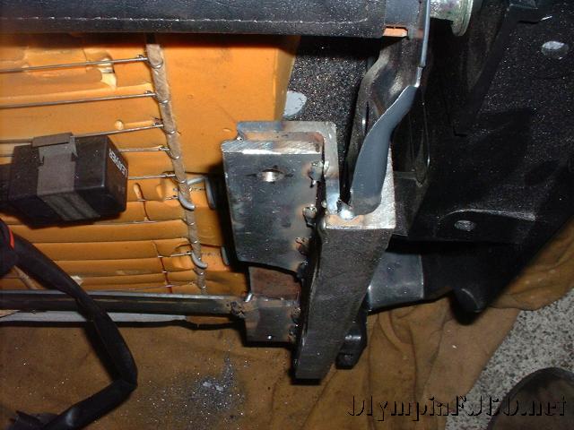
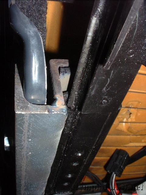
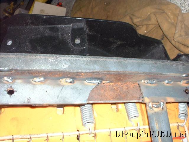
For the radio mounts I decided to remove the factory jack and tool kit. With my lift, the jack doesn’t do much, but I’m going to find a place to put it anyway. The mount for the jack is bolted in on the inner fender and floor of the truck. The Tool bag mount was tack welded to one of the supports. For holding the radios and fuse block, I bent a piece of stainless sheet I had left over from my Off Road Trailer kitchen. I also had some 1″x1/16″ bar for extra support. One bar was bent up to bolt into the lower jack mounting holes, the other runs horizontally from one inner fender support to the other.

image
Radio Mount before installation
image
Radio Mount Installed with Radios
Categories
Tech

Saginaw P/S upgrade on ’84 FJ60

I had a customer that got tired of replacing re-manufactured stock power steering pumps on his Land Cruiser. He wanted to use a Saginaw pump, and was removing the AIR pump at the same time. At first I was going to use a pre-made bracket that directly replaced the stock pump and mounted to the cylinder head. We were also going to have to install and idler in place of the AIR pump, so I decided to mount the P/S pump in place of the AIR pump, to turn the water pump.

I found the correct P/S pump at a wrecking yard on a ’84 Volvo. This pump is important because it has a larger pulley and a metric fitting on the pump outlet that fits the stock Toyota power steering hose.

Photo_052909_001

The bracket pivots the same as the AIR pump. A separate adjuster was need because the size of the pulley did not allow the AIR pump adjuster to fit. Because of the larger diameter pulley, a special length belt was required.

The alternator belt can just be ordered for a truck without Power Steering.

The bracket was made out of 1/4 thick wide bar stock, 4″ wide at the least. It took several revisions to make a bracket that would work on bot the front and the back of the pump. This will make it easier for reproduction. For the front bracket a spacer was needed on the lower whole of .376″.  This is to account for the different depths in the casting. On the rear bracket, a .25″ spacer was needed. For the front spacer, you can just knock the one off of the factory Volvo bracket if you were able to get it. For the back spacer, cutting it off of the same rod you use for the bottom pivot is an option, or knock off and trim the factory spacers. On the rear part of the factory bracket there are two spacers, to space the entire bracket off, but the bottom one is deeper than the top.

Photo_052909_002

For the bottom “pivot” I used 1″ od, 1/2″id steel rod. Think something like 3/4″ od by 1/2″ or 3/8″ id would be better suited for both the pivot and the spacers. The rod was cut to the same length as the bottom of the AIR pump, ~3.8″

To get the proper position for welding, I mounted both the front and rear brackets to the pump, slid the rod through the hole then mounted it into the mount. With the belt attached, I slid the pump into alignment with the water pump and crank then marked the rod. It could be tack welded here, but space is tight and the engine greasy. Once removed, it was talked in several places and reinstalled to check position and alignment. Once every thing checked out, I removed and welded a full bead around both sides of each bracket.

For the top adjuster/cinch bracket, I welded a piece of bar stock on the back bracket. An arc shaped bracket/slide was cut from some scrap steel. Using a section of angle bracket I marked and cut a mount that fits some holes in the block. I forgot to take any pictures of this before letting the truck go, I will try and reproduce this and get updated pictures.

Categories
Tech

FJ60 Heater Core Replacement.

camera-038

Having to install a heater core in the FJ60 Land Cruiser can be one of the worse jobs we have to do. It doesn’t sound bad, but as you start looking into all the steps it becomes apparent this isn’t just a simple operation, or is it. The FSM calls for the dash to be removed, then to remove the A/C evaporator module (if equipped) then the heater core module.

camera-036

The heater core is held in its case by a bracket across the top and little clamps over the tubes. The tubes are held in the heater core with little clips. With the tubes attached there will not be enough clearance to remove the heater core with the case in the vehicle.

camera-037

While you will still need to remove the entire dash and heater ducts. If you remove the tubes first, pull the cases away from the firewall you will be able to remove the heater core without disconnection the A/C. I used a pair of screw drivers to pry the somewhat stuck heater core out of the case. Once out I made sure to clean out any old coolant that was sitting in the bottom of the case. The new heater core did not come with any of the foam that is used to seal the core in the case. All that my local parts store had was camper tape and appears to work just fine. The new core also didn’t come with new o-rings. Having an assortment on hand is always handy and I was able to find two of the proper size.

With the new heater core installed and tubes mounted in place the dash was reassembled, hoses connected at the fire wall and the coolant refilled. It may be advisable to attach the hoses and refill the cooling system before finishing the dash work to spot any leaks.

Categories
Tech

Toyota FJ60 Land Cruiser Seat Upgrade

I have been less impressed with the seats in my ’87 FJ60 since I bought it. They are thinly padded with a weak frame (for someone of my size). I installed seats from a Volvo 240 wagon a few years ago and this was a huge improvement. Better padding, solid frame, just not that adjustable. I regularly pursue the local wrecking yards in search of a better seat that will fit. I have looked at other Toyota seats, BMW, mini-van and others as well. I have never found seats that I thought would both fit, and meet my needs. During a visit to my neighbor hood wrecking yard last summer I came across a Mercedes M350 that had been badly wrecked. They looked like they would fit and both the drivers seat and the passenger had 8 way adjustable power as well as seat heaters.

I never did a write up of the Volvo seats but I will include a few pictures before continuing onto the Mercedes seats.

custom-volvo-seats-004

The factory slider was removed and a bracket was made to fit the Toyota slider to the seats.

custom-volvo-seats-001
custom-volvo-seats-003
custom-volvo-seats-005
custom-volvo-seats-006
custom-volvo-seats-009

I am 6’6″ and the first bracket made the seat sit too high. This left my head in the headliner with the seat back at a comfortable position. I figured I could lower the seat another 1.5″ and modified the drivers bracket to fit this.

custom-volvo-seats-013
custom-volvo-seats-014

custom-volvo-seats-017

This bracket was pretty tight to the slide and it was difficult to adjust when slid all the way back.

Now for the Mercedes seats. This was a much easier bracket to make. Instead of welding angle, all I had to do was bend up some 2″x.25″ bar stock purchased from Lowe’s. To bend the bar I used a little bender from Harbor Freight. This was the max size the bender could handle but it was adequate.

I drew up a sketch in Google Sketchup with measurements from the truck floor. Now, the floor pan on the ’86 and ’87 trucks is different than the earlier trucks. The earlier trucks have a higher raised spot that the sliders attach to. This may be enough that these seats would not fit for tall people.

Once I had my brackets I drill the floor mounting holes and loosely bolted them to the floor. I then set the drivers seat in the truck to get an idea of location. Once selected, I marked the brackets for drilling the seat mounting holes. Brackets bolted to the seats it was time for test fit. I got lucky on this one and the seats fit. They still sit a little high in the back and I have to have the rear adjusted all the way down with the front all the way up. I have room to lower the back of the bracket about 2″. I will add photos to this article once I have reworked the brackets.

Now for the wiring. There are two types of seats in the ML350, power with memory and just power. I ended up with the power with memory. The power only may have been a little easier to wire but this is what I had. On the power with memory seats, each seat has a power seat module (PSM). This is a little relay/computer box that is attached to the bottom of the seats. All of the motors and motor sensor connect to this box as well as input from the vehicles extended activity module (EAM). My seats came with the PSMs (be sure to get the harness from the car to the PSM). The EAM performers many functions in the car none of which are needed here except power to the PSM.

It was a little confusing at first but I figured out the wiring. There is two power inputs to the PSM, 12v+ 30amp to the seat functions and 12v+ 20amp for the seat heaters. There is also a ground wire, and two wires to the heated seat switch. There are two positions for the seat heaters, regular and rapid heat (hi). This again had me confused for a while as I kept trying to apply 12V+ to the wires with no action from the relays. After looking at the wiring for a 4th or 5th time, going to the computer to do some additional research, it dawned on me that the heater relays may be controlled with 12v-. After a few tests I had completely functioning power heated seats.

Is it worth it? I think both the Volvo seats and the Mercedes seats are a great improvement. Not only do they look good (leather), but the are more comfortable and have a much more rigid frame. I think with the ease that the Mercedes brackets were made and how nicely they fit in the 60, the would be my preference every time. They may be much harder to find though.

Categories
Tech

H55F into an Early FJ60 Land Cruiser

I recently installed an H55F Transmission into a 10/84 built ’85 FJ60. It is commonly known that the H55F is a direct installation, and upgrade, into a 5/85 and later FJ60. There are several writeups detailing the later installation. I had always heard that the earlier trucks were much more difficult but thought I would give it a try.

The H55F offers a few benefits over the stock H42 4 speed transmission found in the US market. It has a overdrive 5th gear. In our over 55 freeway speeds this can be a blessing, it reduces the RPMs and noise. It also offers a lower 1st gear. If you do much offroad, this can be a big help in 4 low.

4-5speed

At first glance, the H55F looks the same as the early H42. The most noticeable difference is the extension housing making it 3 1/2 inches longer. This is were the the fifth gear is located. It also has the transfercase shifter mounting moved back a little and out.

If you haven’t rebuilt the transfercase this is an excellent time. You will need to replace the case gaskets regardless and most of the labor to rebuild it will be done. The only other parts to the rebuild is to replace the bearings.

tcase_shifters
5_speed_bolts

The major difference between the early and late swaps are the few extra parts and modifications you will need. The drive shaft lengths will need to change (the front lengthened and the rear shortened by about 3.5″). Also you will need to modify the transfercase shifter or get the shifter from the later H42. I did not feel comfortable cutting and welding the cast lever and so I turned to SOR for the lever parts. You will also need the longer transfercase to transmission bolts from the later transfercase. While it is possible to use the 4speed shifter lever, the 5speed lever is a better fit and does not require modification to miss the dash.

First step is to remove the drive shafts, cross member, and disconnect the speedometer cable, ground wire and wiring harness. Using a suitable transmission jack, remove the transmission and transfercase as one piece. Carefully disassemble the transfercase per the factory service manual. Make sure to note the order of the various parts such as the speedometer gear and spacers.

center_bolt_hole
oiler_cup

Before you start to assemble the transfercase to the new H55f take note of a few things. First, on the later transfercase, you will need to plug the center bolt hole on the forward case half, using a 1/4 pipe thread tap and plug. The early case does not have this hole. The 5th gear oiler cup will also need to be installed. Unlike the other gears in the transmission and transfercase, the 5th gear is not splash oiled. Without this cup, you may quickly burn up your 5th gear.

Install a new input shaft seal in the front case half, then install a new gasket between the transmission and transfercase. This is were you need the longer bolts from the later transfercase. It is important to use a liquid sealer on the bolts that secure the front case half to the transmission. Before putting the input gear onto the input shaft, install the idler gears on the idler shaft. Continue assembly as normal.

5_speed_install_23

Once the transfercase is mounted on the transmission, the complete unit can be reinstalled into the truck. The rear mount and cross member will bolt up just as it did with the H42. Now install the longer set of transfercase shifters. Make sure you get the the shifter guide when you order your shifter parts. Now is when you want to take the measurements for the front and rear drivelines. It should be a 3 1/2 inch change from the current lengths, but be sure and measure. Make sure to check with the shop doing the work to see what they want you to measure. Most of the time it will be flange to flange. It is best to measure with the vehicle on the ground. A 1 inch collapse should be plenty (this is how much shaft can travel to full compression). Also make sure the shaft is in phase before installing in the truck.

front_shaft_clearance

I was concerned with the clearance of the front driveline and the transmission crossmember, but with the double cardon joint on the earlier trucks it has no problem. Here are a few pictures to compare the difference between and H55F in an early FJ60 and a late FJ60.

The transfercase boot may need a little trimming to fit around the new shifter. It may be difficult to get the 5speed into gear at first.  Here is a summary of some of the possibilites (cruiserparts.net is another source for the 5speed and shifter parts).